Baldor Industrial Motor wiring diagram
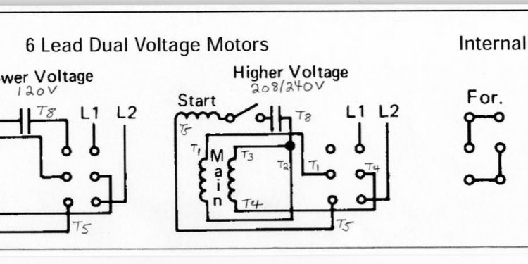
 Im trying to wire a unique motor to a variable frequency drive (VFD) and having some trouble figuring out how-to wire the motor towards the VFD. The motor is a 1 HP, 3-phase, 208-230/460 volts, and I also'm wiring a 120 VAC offer voltage into the VFD, which tips that around 3-phase 230 V. We have included a picture of the wiring drawing connected to the motor below.
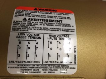
Centered on that drawing therefore the proven fact that the motor will undoubtedly be run at 230 V, we gather that wires 9 and 3, 8 and 2, 7 and 1, and 4 and 5 and 6 all should be wired collectively - providing me 4 individual cable bundles. The VFD features wire terminals for U, V, and W, so that it appears like I have 3 terminals and 4 wires, therefore I'm not sure which wires go right to the U, V, and W terminals on VFD or how to proceed with the additional wire bundle. I have included a picture regarding the motor wiring diagram through the VFD manual the following.
I became thinking that the additional wire bundle would-be a floor, but there is however in addition a green screw inside the wiring field regarding the motor that i am thinking is where I connect the floor cable (and connect another end on defensive planet PE terminal from the VFD), but kindly correct me personally if I'm wrong. With the extra line, I'm additionally remaining wondering tips separate between U, V, W and regardless of the 4th cable is. Inside VFD motor wiring diagram, In addition can't figure out what the Physical Earth Shielding (PES) is - could it be simply saying to utilize shielded cables and attach the shield to surface? The design figures for products are: Baldor CEM3546 Motor, and Lenze SMVector ACtech ESV751N01SXB. So my particular concerns are:
- What's the 4th line?
- Where do we connect the 4th cable?
- To ground the motor, do we attach a line amongst the green nut and the PE (protective planet) terminal from the VFD?
- By connecting the ground line from the incoming 120 V single phase to this same PE terminal, could be the engine grounded?
Share
Related

Latest blog posts


